Debugging Hardware SPI on ATMega2560
This article talks on ATMega2560, instead of the usual focus on ATMega328. Discussions of this article may or may not relate to the latter’s hardware.
The world of Arduino keeps throwing surprises.
While working on my recent project PPPP (or P4), I came across a rather weird observation, that no ILI9341 hardware driver/ software library was able to support HWSPI on Arduino Mega officially. Although they provide APIs for SWSPI (SoftWare SPI), it clocks at about 60-100 kHz, painfully slow compared to the builtin 4 MHz HW.
Screen Refresh Rates
I have made many projects involving LCD displays, and the ILI9341 driver specifically, but I’ve always used the breakout with the 8-bit interface (which requires 2 clock cycles) to dump data into the screen. It saves a lot of mess of wiring and is fairly easy to use.
This time, however, due to design constraints, I ended up using a display with a straight SPI interface. Apart from that, P4 needed a lot of peripherals to be installed, so I did not want to waste any GPIOs just to increase frame rate. This meant a 8x reduction in the screen update speed, but at 4 MHz, 16-bit wide 320x240 pixels can be uploaded in about 0.3 seconds.
Now 3 FPS for a low power handheld device’s touchscreen is actually a decent refresh rate, because I only wanted to support GUI, it’s not like I wanted to play CS:GO on it. Only at this point, I did not know what a quagmire I was getting myself into.
The display hosts a ILI9341 driver and a XPT2046 touch controller. Adafruit’s library just did not work with HW-SPI constructor, as it didn’t for Great Scott. I tried several other native libraries, as well as overkills including UCGLib.
The only choice I had, at this point in time, was to simply go ahead with SWSPI, which seemed unfortunate because some brilliant people were able to clock the ILI9341 at 48 MHz, 7.2 times the rated ‘optimal’ of 6.66 MHz ref.
Troubleshooting
I got my Oscilloboi out and had a look at the signals, which revealed what the SPI bus was doing. Actually, the ILI9341 has a 3.3V logic level, and the AVRfamily of microcontrollers are designed for 5V. What this meant was that the SPI logic was indeed working, but the Arduino wasn’t picking up any responses because of a mismatch in the voltage levels.
A solution is to use a bidirectional logic-level shifter. They are pretty cheap and have the following schematic:
| Bi-Directional Logic Level Shifter |
|---|
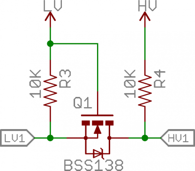 |
This image has been stolen from SparkFun’s tutorial on logic-level shifters. They talk about how to wire it up and everything, except that they don’t mention where this design wouldn’t work!
The problem is that the SPI drive on the ADC161S626 or the ILI9341 is not enough to feed ATMega2560’s MISO line directly. Typical logic-level shifters (Sparkfun’s design) works only for open-collector (open-drain) devices. This means that it relies on the pullup resistors to pull-up the values from 0 to either HV or LV. This is good for low frequency protocols, like one-wire, or I2C clocked at 400 KHz. But this design fails for the SPI protocol as it is meant to be driven actively in both directions, which is called a push-pull, or a totem pole configuration. The active drive is required because for a fast enough rise time to achieve a 4 MHz clock, the value of the pullup resistor becomes very small, which is never a good idea for signals.
Solution
Obviously, there exists a solution. Texas Instruments’ TXS0108E is a full duplex logic level converter which is built exactly for logic level conversion between totem-pole configurations.
Using it as an intermediate for the connections between ATMega2560’s HWSPI and the ILI9341 SPI interface enables this device easily.